

Wayne Foulds: A gentleman and a scholar.
Posted by Picasa
Thursday, June 30, 2005

Wednesday, June 29, 2005


Tuesday, June 28, 2005


Sunday, June 26, 2005
Current Transformers

If you have worked at Mountainview and have been involved with wire pulling or termination you have probably run into a few CTs or Current Transformers. So how does a Current Transformer differ from a Power Transformer (also known as a Voltage Transformer)? Not by as much as you would think. Normally we don't think of transformers in terms of current. Voltage comes into a transformer at 480 volts and is stepped down to 208/120 volts for instance, but nothing changes for free. For the voltage to step down, the current had to step up. That's why the 480 volt leads are smaller than the 120/208 volt leads on a power transformer, larger current means larger wire. In the case of a CT, wire is wound around a laminated iron core in the shape of a doughnut. The wire in which the current is to be measured passes though the hole in the center of the CT which has a polarity mark H1. This could be considered as the primary of the transformer. The secondary side of the CT is marked X1 and X2. This is where the similarity between VTs and CTs end. CTs must remain shorted between X1 and X2, either by a jumper or by an ammeter or some other low resistance device or disaster will result. As electricians it is our experience that voltage is a constant while the current varies with the resistance or impedance of the circuit. When a light is turned on, current flows and is determined by the resistance of the filament in the light. The voltage drop across the lamp is insignificant and we would still measure 120 volts before and after the light was turned on.
Posted by Hello

In the world of Relay Technicians Impedance remains the same and voltage drives the current in the circuit. Lets go back to the CT and we will say that the CT has a ratio of 2000 to 5. That means if 2000 amps are flowing through the primary wire, there will be 5 amps flowing from X1 to X2 in the CT. CTs exist because it is impractical to make a 2000 amp ammeter. The manufacturer designs the ammeter to read full scale at 5 amps, so a 2000 amp ammeter must have a 2000:5 CT in order to read correctly. When 2000 amps flow through the primary wire, a magnetic field is produced that is proportional to the current. This magnetic field induces a voltage in the CT, but because the CT is shorted the voltage will drop significantly. If you were to try and measure the voltage at the X1 and X2 terminals you would find that the meter would read almost 0, giving the illusion that a CT has only current flow. This voltage drop is largely due to the fact that there is only one turn in the primary circuit. If you were to short the secondary of a power transformer, the magnetic field in the core would drop, lowering the impedance in the primary circuit and high current would flow in the primary. In a CT, shorting out the secondary also caused the magnetic field to lower in the core, but the single turn of wire cannot replace the magnetic field in the core, therefore the short has no effect on the primary wire. If, however, the CT were not shorted the 2000 to 5 Current Transformer would become a 5 to 2000 Power Transformer and on an 18kV line there would be 7,200,000 volts at the X1 and X2 terminals. Let me say that again, SEVEN MILLION, TWO HUNDRED THOUSAND VOLTS. This is why we use ring terminals on all CT circuits so even if the screw were to become loose it might not fall off altogether.
Posted by Hello
Saturday, June 25, 2005


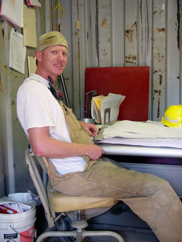
I may look happy but I'm in the process of sanding wires before termination. Actually I had to de-term the wires, sand them and then re-terminate them. All that and I didn't even get to hump the generator!
Posted by Hello

This is the wire in question. After stripping the wire, it had to be sanded to get the blue crap off. This will be the first time I had to bring sand paper to terminate, and don't think it wasn't a joy to sand a hundred #14 wires with emery cloth.
Posted by Hello


Little Billy Reno, or should I say SOAPY-SOAPY!. Pulling wire in the LEC.
Posted by Hello
Friday, June 24, 2005

Thursday, June 23, 2005

John Harrison at the GE LEC. Power from the Excitation Transformer gets rectified into DC in the LEC. Some of the bus work is visible in the background.
Posted by Hello

Brad Kobler is working with the GE engineers to get CTG 3A ready to fire in July. Brad is on the top of combustion turbine, waiting for instructions from GE
Posted by Hello
Wednesday, June 22, 2005

Marcus Blackwell and John Martinez working late in the STG3 on the wirepulling crew. Ten hours of work in the summer heat. I'm going to drink a cold brew in honor of you guys!
Posted by Hello
Monday, June 20, 2005

Sunday, June 19, 2005

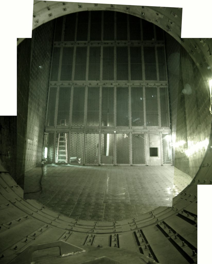
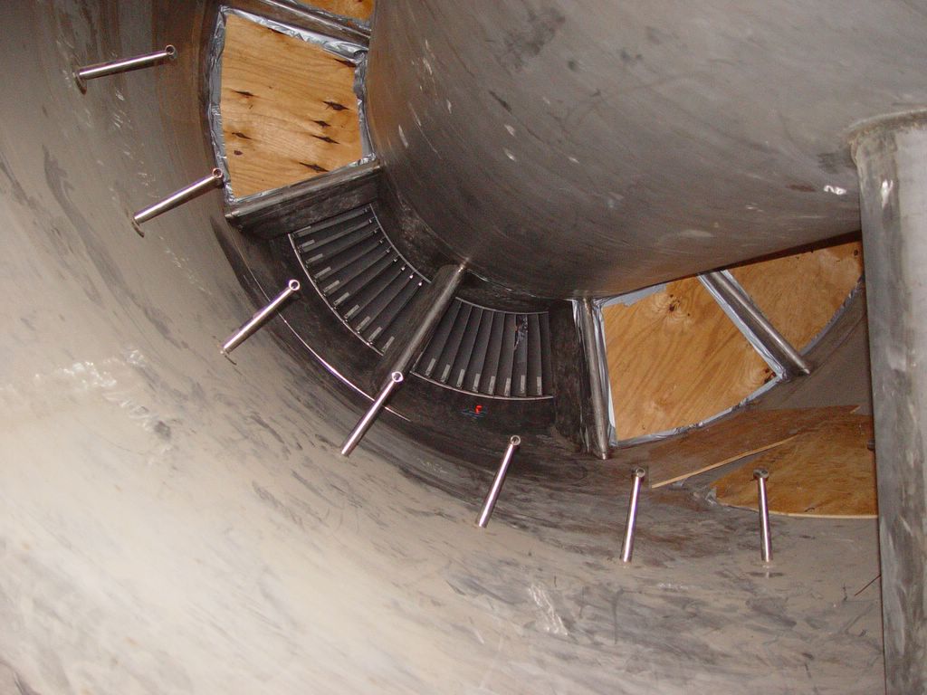
Composite photo of diffuser panel. The exhaust exits into this large chamber and through a series of small holes in a stainless steel wall. Past the wall are hundreds of tubes that will absorb the heat from the combustion turbine.
Posted by Hello

Mountainview in a nutshell

(Click on photo to enlarge) This is a simplification of the power distribution at Mountainview, but generally this is how the plant works. When the plant is not generating power, it still needs power to run the systems necessary to start, so power is brought into the plant by the very same power lines it will use to feed the grid. This condition is called "back feeding". 230,000 volts is applied to the main transformer which steps the voltage down to 18,000 volts. The power is then fed to the Unit auxiliary Transformer or UAT which steps the voltage down to 4,160 volts. This voltage allows the Circulation Pumps, which are the large motors in front of the cooling towers to move cooling water through the plant, as well as the gas compressors and feed water pumps. The voltage is also stepped down to 480 volts through the load center transformer, which provides power for smaller motors, UPS systems, and other lower voltage systems to run the plant. Strange as it may seem, in order to make AC power, you need DC power, so the Excitation Transformer steps the 4160 volts down to 380 volts and rectifies it. It then sends this voltage to slip rings in the Generator Collector. When the north and south poles in the rotor spin past the stator polls, an alternating current will develop, generating 18,000 volts AC. In order to get the rotor spinning, however, we must first start the turbine. This is done through the Static Start transformer, which steps up the 4,160 volts to 2,080 volts and then through a variable frequency drive directly to the Isophase bus. This will turn the generator temporarily into a motor which will spin the combustion turbine. Once the turbine is up to speed, fuel is applied and ignited and the generator will begin making power. The last step in the process is closing the generator breaker. In order to do this, the generator and grid must be in synchronization. A special relay called a synch relay watches both the rotating magnetic field of the grid and the generator. The generator will spin slightly faster than 60 hertz, and when the phases are within a critical angle and voltage, the breaker switch is closed and the phases will be locked together.
Posted by Hello
Friday, June 17, 2005
It's big and scary and I hope they don't throw the switch
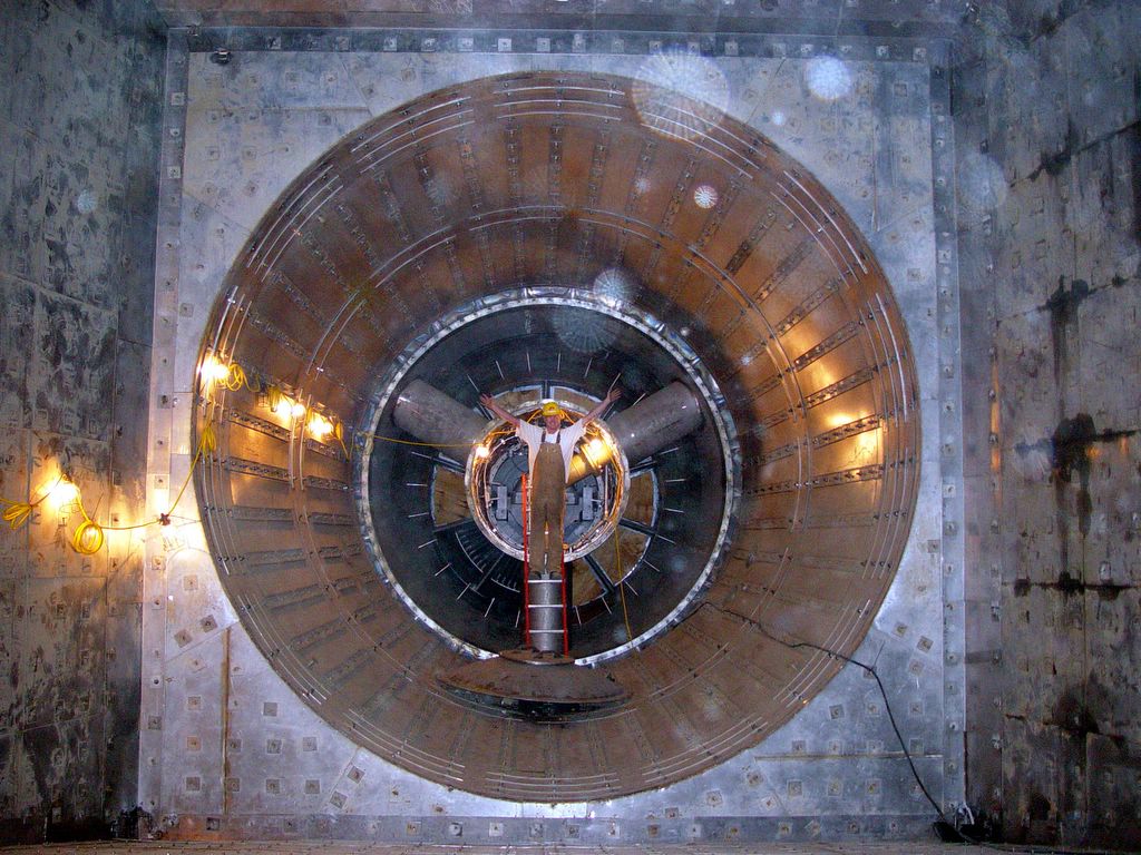
This photo gives the scale of the exhaust area. Doug Childers is standing in front of the bearing chamber. You will also notice some round circles that look a little like snowflakes. I believe these are the spirits of Indians who are trying to communicate their displeasure with Bechtel building a power plant on ancient burial grounds...or just dust.
Posted by Hello

Thursday, June 16, 2005
Get me a guy!
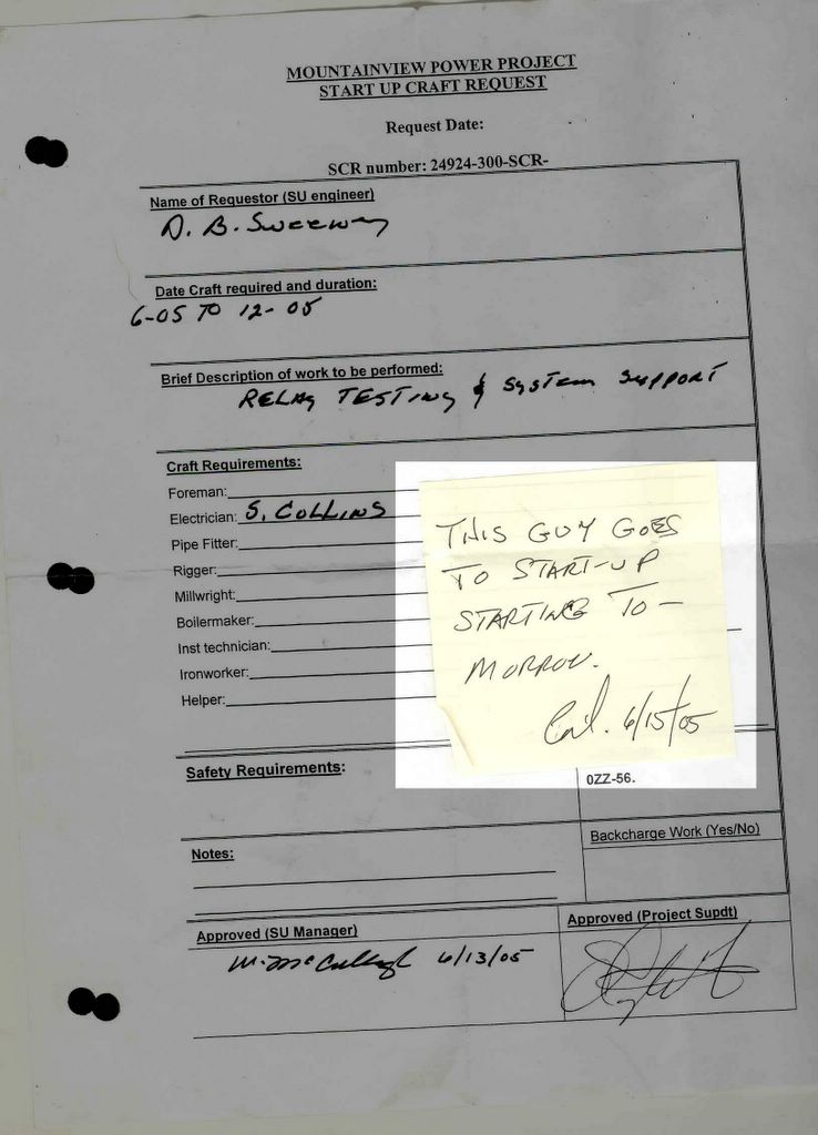
I need a box of six penny nails, some roof tar and, oh yeah, get me a guy.
Downloaded by Hello

Wednesday, June 15, 2005

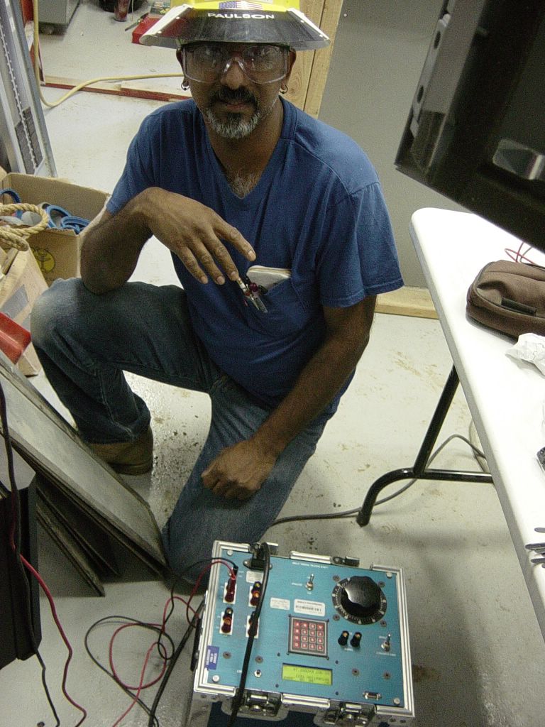
Infrared Photo of me inside the bearing housing just before they turned on the blower. Luckily I was outside by that time or I would have been as white as I look in the photo.
Posted by Hello

This is a composite photo of the business end of the combustion turbine photographed in infrared
Posted by Hello

In this photo the exhaust turbine blades are covered by plywood. The chamber in the center holds the bearings and the end of the turbine shaft. There are also pipes that deliver cool air to the bearings. When the turbine is ready to fire, the bearing chamber will be covered by a steel door.
Posted by Hello
Tuesday, June 14, 2005
Temp Power to the rescue

Ed Thacker, Lauren Citron, and Fred Delpino discuss a plan of action before routing temp power cables.
Posted by Hello
DO NOT HUMP GENERATOR

No, I'm not making this up. There really is a sign that says "DO NOT HUMP." When did this become a problem? It also seems like it might be a little uncomfortable! Actually this is a sticker that was applied by railroad company's to warn against damaging the generator from a practice called HUMPING. Some switch yards use a hill or "Hump" to sort rail cars. A string of cars are detached one at a time and pushed over a hump. The hump accelerates the cars and a person in the switching station sends the cars to the proper rail in the yard by electrically switching the tracks. In the case of the generator, a sticker saying "DO NOT HUMP" was placed on it so that the yard personnel would set the rail car with the generator aside for special handling. Sometimes the practice of humping damages loads because there is no control as to how fast the car will travel once it's humped.
Downloaded by Hello

Sunday, June 12, 2005

Robert Walker Under the PEECC (which in case you're wondering, stands for "PACKAGED ELECTRIC AND ELECTRONIC CONTROL
COMPARTMENT"
Downloaded by Hello

Saturday, June 11, 2005

Mike Brown is the M.C. and one of the musicians for a musical jam session, also staring Wayne Foulds on Bass. The Music Starts at 4:00 pm on July 16 (Click on photo to enlarge)
Posted by Hello
Wednesday, June 08, 2005


Subscribe to:
Posts (Atom)
Older Posts