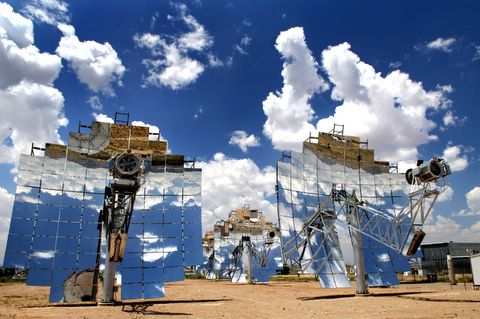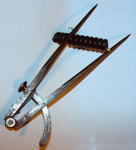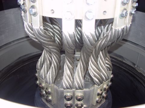
A model of the stirling engine. This device converts heat directly to mechanical motion, which can then be converted to electricity by attaching a generator. This type of engine has been around since the internal combustion engine, but has never been practical in something like an automobile. The Stirling Engine, however, is perfect for generating power from solar heat as you will see in the following photos.
Posted by Scott Collins (Click to Enlarge Photo)
Older Posts
Saturday, December 31, 2005
Wednesday, December 21, 2005
Saturday, December 17, 2005
Stabed in the back
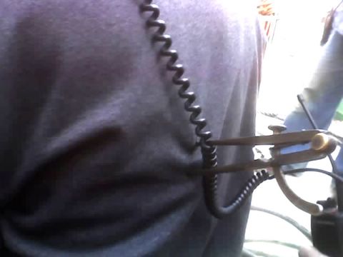
I would like to say this is one of my photoshop creations, but this is an actual photo (the best I can get from a camera phone,) of Brian Khairulla with a 7-inch compass sticking out of his back. He was working near the stacks on 4a when one of the insulators dropped a compass from about a hundred feet up. Mark Edwards and James were working next to him when they heard a thump. Mark attempted to remove the compass, but it seemed to be imbedded into a rib. Safety and Rescue workers imobilized the compass and transported him to Loma Linda where doctors plucked the compass from his back. By a stroke of luck, there were no organs affected and it had not actually hit any bone, but was imbedded in the muscle instead. Brian left emergency a few hours later with some bandages and some happy pills. Later we're going to buy him a six pack of Mikes Hard Lemonade for this little trick!
Posted by Scott Collins (Click to Enlarge Photo)
Sunday, December 11, 2005

The brown box to the right is one of the PTs or Power Transformers. The PT transforms the 18,000 volts of the Isophase Bus to 69.3 volts Phase to Ground (120 volts phase to phase). This voltage is sent to the Generator Protection Panel in the STG E-house, where it is monitored for proper level and frequency. The device on the left is a lightning arrestor which is also connected to the Isophase. The Silver ring through with the Isophase is passing through is one of the CTs or Current Transformers. The ratio of the transfomer is 10,000 to 5, so that if 2000 amps is flowing on the Isophase, 1 amp of current will circulate through the CT circuit back to the Generator protection panel where relays will monitor the current level, phase angle, phase imbalance, phase fault distance, and most important, current differential.
Posted by Scott Collins (Click to Enlarge Photo)

It' doesn't look much like what we would normally call a breaker, but this is a view of the Generator Breaker up on STG 4. The two red rings are part of the Disconnect and connect together by the use of a hand crank. The part after the two red rings is the Breaker. The contacts are sealed in a vacuum to prevent arcing during opening.
Posted by Scott Collins (Click to Enlarge Photo)
Tuesday, December 06, 2005
Sunday, December 04, 2005
Older Posts


