Older Posts
Friday, July 29, 2005
Thursday, July 28, 2005
Wednesday, July 27, 2005

At the Mountain View Power Plant, a majority of electrical protection involves relays and is broken down into the following: Line Protection, Generator Protection, Transformer Protection, and Motor Protection. Before the new generations of electronic relays were developed, protection was provided by mechanical relays with each relay providing a particular type of protection.
Posted by Scott

The new generation of electronic relays can take the place of many mechanical relays. One electronic relay can respond to a variety of fault conditions which may include: Instantaneous Overcurrent, Time Overcurrent, Differential Overcurrent, Ground Fault Overcurrent (Zero Sequence), Current Imbalance (Negative Sequence), Under/Over Voltage, Under/Over Frequency, Loss-of-Field, and Phase Distance to name a few.
Posted by Scott

In previous posts the mechanics by which Current Transformers convert high current flow in a conductor to a lower, easier to measure current was described. This is important when faults occur because of the resulting high current flow from a phase-to-phase or phase-to-ground fault. When a fault does occur, it is important not only to clear the fault as quickly as possible, but also to disconnect only what is needed and not shut the entire plant down if possible. This means that the equipment not only needs to sense a fault, but establish where the fault is occurring. If a fault occurs in Generator 4a, for instance, high current will flow from all the other generators on line as well as the rest of the grid. The motors that are circulating water and supplying fuel to the generators would also suffer from a generator fault, as the voltage drop will cause high current to flow in the motor windings. It would make little sense to trip all six generators, and all the transformers, and all the motors because one generator was shorted One of the schemes to locate a fault is Differential Fault Protection. Instead of using one Current Transformer to detect a fault, two are employed. In this diagram two C.T.s are used to protect a transformer. The C.T.s are connected in series, but the polarities are different.
Posted by Scott
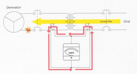
If a fault occurs at the generator, the current will flow through the transformer and current will circulate through the C.T.s circuits in the same direction, however, no current will flow through the Differential relay (pictured here as an Ammeter). This would allow the generator protection to open the breakers and disconnect the generator but keep the transformer breaker closed. This would be important if another generator was connected to the same transformer.
Posted by Scott

If the fault occurs somewhere beyond the generator and transformer, the current would flow from the generator, through the transformer and out to the line. Again, current would circulate through the C.T. Circuit in the opposite direction, but none would flow through the relay allowing some other protective device to clear the fault.
Posted by Scott

If, however a fault were to occur in the transformer or anywhere in the zone of protection, current would circulate in the C.T. circuit in two different directions, forcing current to flow through the relay. The relay would then open the necessary breakers to isolate the transformer from the rest of the plant.
Posted by Scott
Friday, July 22, 2005
Thursday, July 21, 2005
Tuesday, July 19, 2005
Saturday, July 16, 2005
Wayne Foulds playing bass guitar at the Bro-Jam

Wayne Foulds was just one of the many musicians at the Bro-Jam in Wrightwood California. To see more photos from the jam click on this link www.brojam.blogspot.com
Posted by Picasa
Friday, July 15, 2005
Older Posts


